The Xaap Inspection Tool Suite
The Xaap inspection tool suite is composed of two primary parts:
|
|
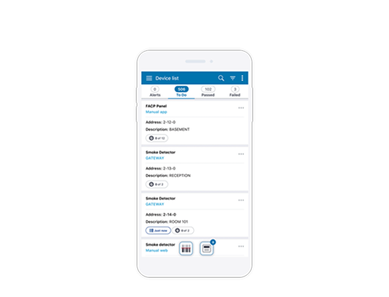
By using the gateway, the suite enables inspectors to pull inventory from a Fire Alarm Control Panel (FACP), test addressable devices on the panel, and send commands back to the panel. The inventory and results of the inspection are all saved to the Xaap cloud service. They are accessible through the mobile application and can be used to generate reports.
Supported Panels
The gateway is compatible with the following FACP panel models:
- 4100ES
- 4010ES
- 4007ES
It does not support the 4006 or 4004ER.
The Gateway Components
The unboxed components of the gateway consist of:
- The gateway itself
- Two Wi-Fi antennae which screw on the back of the gateway
- A power cord
- A regional plug adapter
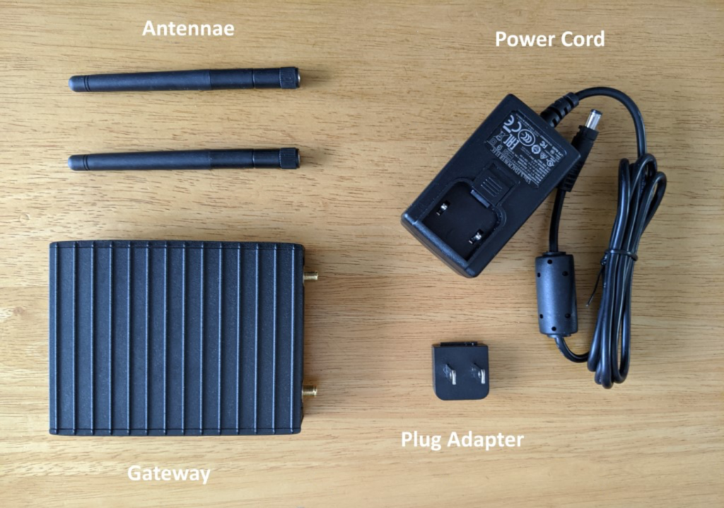
Figure 1
The gateway is based on an off-the-shelf general purpose IoT gateway, supplied by the company Compulab. In the following description, we will focus only on the connectors and ports relevant to Xaap.
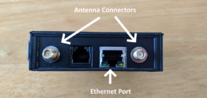
Figure 2
The back of the gateway (see Figure 2) has two connectors for the antenna. These should be screwed on here before using the gateway. Wi-Fi connectivity is significantly impacted if they are not used.
The Ethernet port between the connectors is the only port that should be used if you want to avail of that connectivity option. It also supports Power Over Ethernet (POE). If it is connected to an Ethernet switch or equivalent device that supports this feature, you can power the gateway from this port instead of using a power cable.
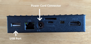
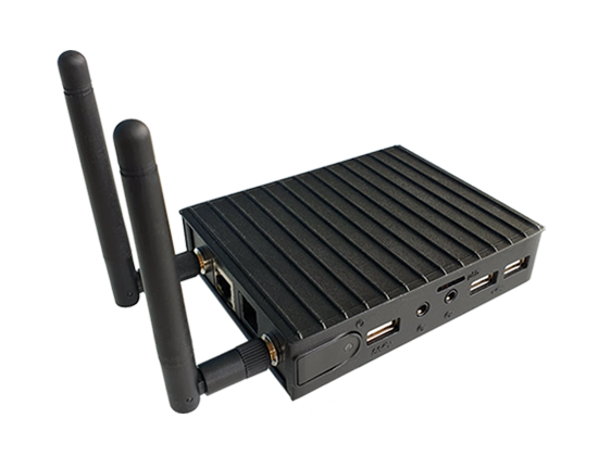
Figure 3
On the right side of the gateway (see Figure 3) you see the power cord connector. Insert the power cord into this and twist it to secure it in place. There is also a USB port, which can be used for connecting either a supported USB modem or the USB to serial adapter for the fire panel cable, which will be described later in this document. All other ports are not used by the Xaap gateway. In particular, the Ethernet port on this side of the gateway is not supported and it will not provide Ethernet connectivity!
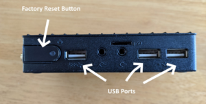
Figure 4
On the left side of the gateway (see Figure 4) there is the factory reset button along with three additional USB ports.
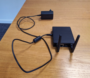
Figure 5
Figure 5 shows the assembled gateway with antenna and power cord attached.
What’s next?
- Connect the Gateway to a Fire Panel
- Connect the Gateway to the Xaap Cloud
- Perform an inspection using the Gateway
If you are new to our mobile application we have a great set of articles to help you get started.